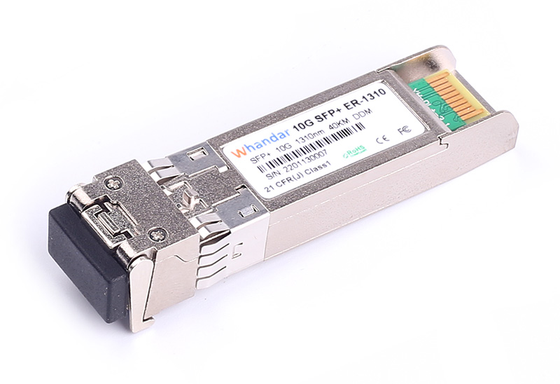
Product Description
Features
ü Hot-pluggable SFP footprint
ü Duplex LC fiber connector
ü Transmission distance up to 40Km on 9/125µm SMF
ü Built-in DDMI functions
ü Comply with SFP MSA .
ü Single +3.3V power supply
ü RoHS6 compliant (lead free)
ü Operating case temperature:
Commercial : 0 to +70°C
Industrial : -40 to +85°C
ü Comply with Ethernet Switches from a lot of widely used brands .
Applications
ü 10GBASE Ethernet
ü SONET OC-192 SDH STM-64
ü Switch to Switch interface
ü Router/Server interface
ü Other optical transmission systems
Optical Characteristics
Parameter | Symbol | Min | Typical | Max | Unit | Notes |
Transmitter |
Centre Wavelength | λc | 1270 | 1310 | 1350 | nm |
|
Spectral Width(-20dB) | Δλ |
|
| 1 | nm |
|
Side-Mode Suppression Ratio | SMSR | 30 | - |
| dB |
|
Average Output Power | Pout | -1.0 |
| +3.0 | dBm | 1 |
Extinction Ratio | ER | 3.5 |
|
| dB |
|
Data Input Swing Differential | VIN | 180 |
| 850 | mV | 2 |
Input Differential Impedance | ZIN | 90 | 100 | 110 | Ω |
|
TX Disable | Disable |
| 2.0 |
| Vcc | V |
|
Enable |
| 0 |
| 0.8 | V |
|
TX Fault | Fault |
| 2.0 |
| Vcc | V |
|
Normal |
| 0 |
| 0.8 | V |
|
Receiver |
Centre Wavelength | λc | 1260 |
| 1600 | nm |
|
Receiver Sensitivity |
|
|
| -16 | dBm | 3 |
Receiver Overload |
| 0.5 |
|
| dBm | 3 |
LOS De-Assert | LOSD |
|
| -17 | dBm |
|
LOS Assert | LOSA | -30 |
|
| dBm |
|
LOS Hysteresis |
| 0.5 |
|
| dB |
|
Data Output Swing Differential | Vout | 300 |
| 900 | mV | 4 |
LOS | High | 2.0 |
| Vcc | V |
|
Low |
|
| 0.8 | V |
|
Notes:
1. The optical power is launched into SMF.
2. PECL input, internally AC-coupled and terminated.
3. Measured with a PRBS 231-1 test pattern @10312Mbps, BER ≤1×10-12.
4. Internally AC-coupled.
Pin Descriptions

Pin | Signal Name | Description | Plug Seq. | Notes |
1 | VEET | Transmitter Ground | 1 |
|
2 | TX FAULT | Transmitter Fault Indication | 3 | Note 1 |
3 | TX DISABLE | Transmitter Disable | 3 | Note 2 |
4 | SDA | SDA Serial Data Signal | 3 |
|
5 | SCL | SCL Serial Clock Signal | 3 |
|
6 | MOD_ABS | Module Absent. Grounded within the module | 3 |
|
7 | RS0 | Not Connected | 3 |
|
8 | LOS | Loss of Signal | 3 | Note 3 |
9 | RS1 | Not Connected | 3 |
|
10 | VEER | Receiver ground | 1 |
|
11 | VEER | Receiver ground | 1 |
|
12 | RD- | Inv. Received Data Out | 3 | Note 4 |
13 | RD+ | Received Data Out | 3 | Note 4 |
14 | VEER | Receiver ground | 1 |
|
15 | VCCR | Receiver Power Supply | 2 |
|
16 | VCCT | Transmitter Power Supply | 2 |
|
17 | VEET | Transmitter Ground | 1 |
|
18 | TD+ | Transmit Data In | 3 | Note 5 |
19 | TD- | Inv. Transmit Data In | 3 | Note 5 |
20 | VEET | Transmitter Ground | 1 |
|
Notes:
Plug Seq.: Pin engagement sequence during hot plugging.
1) TX Fault is an open collector output, which should be pulled up with a 4.7k~10kΩ resistor on the host board to a voltage between 2.0V and Vcc+0.3V. Logic 0 indicates normal operation; Logic 1 indicates a laser fault of some kind. In the low state, the output will be pulled to less than 0.8V.
2) Laser output disabled on TDIS >2.0V or open, enabled on TDIS <0.8V.
3) LOS is open collector output. Should be pulled up with 4.7k~10kΩ on host board to a voltage between 2.0V and 3.6V. Logic 0 indicates normal operation; logic 1 indicates loss of signal.
4) RD-/+: These are the differential receiver outputs. They are internally AC-coupled 100 differential lines which should be terminated with 100Ω (differential) at the user SERDES.
5) TD-/+: These are the differential transmitter inputs. They are internally AC-coupled, differential lines with 100Ω differential termination inside the module.
Ordering information
Part Number | Product Description |
HD-SFP+/10G-ER-1310 | 1310nm, 10Gbps, LC, 40km, 0°C~+70°C, with DDM |
HD-SFP+/10G-ER-1310-I | 1310nm, 10Gbps, LC, 40km, -40°C~+85°C, with DDM |


 sales@huahanda.com
 0755-86654236