Product Description
Features
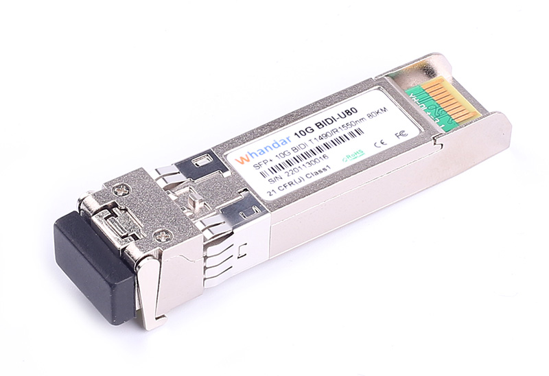
Hot-pluggable SFP footprint
Simplex LC fiber connector
Cooled EML transmitter and APD receiver
Transmission distance up to 80Km on 9/125µm SMF
Built-in DDMI functions
Comply with SFP MSA .
Single +3.3V power supply
RoHS6 compliant (lead free)
Operating case temperature:
Commercial : 0 to +70°C
Industrial : -40 to +85°C
Comply with Ethernet Switches from a lot of widely used brands .
Applications
10GBASE Ethernet
SONET OC-192 SDH STM-64
Switch to Switch interface
Router/Server interface
Other optical transmission systems
Optical Characteristics
Parameter | Symbol | Min. | Typ. | Max. | Unit | Note |
Transmitter |
Average Launched Power | PO | 0 | - | 4 | dBm | HD-SFP+/10G-BIDI-80U |
|
| -1 | - | 3 | dBm | HD-SFP+/10G-BIDI-80D |
Average Launched Power(Laser Off) | Poff | - | - | -30 | dBm | Note (1) |
Center Wavelength Range | λC | λ-7.5 | λ | λ+7.5 | nm | Note (2) |
Side mode suppression ratio | SMSR | 30 | - | - | dB |
|
Spectrum Bandwidth(-20dB) | σ | - | - | 0.3 | nm |
|
Extinction Ratio | ER | 8.2 |
| - | dB | Note (3) |
Output Eye Mask | Compliant with IEEE 802.3ae |
| Note (3) |
Receiver |
Input Optical Wavelength | λIN | 1480 | 1490 | 1500 | nm | HD-SFP+/10G-BIDI-80U |
1540 | 1550 | 1560 | nm | HD-SFP+/10G-BIDI-80D |
Receiver Sensitivity | Psen | - | - | -23 | dBm | Note (4) |
Input Saturation Power (Overload) | PSAT | -6 | - | - | dBm | Note (4) |
LOS Assert | LOSA | -38 | - | - | dBm |
|
LOS De-assert | LOSD | - | - | -24 | dBm |
|
LOS -Hysteresis | PHys | 0.5 | - | 8 | dB |
|
Note:
1. The optical power is launched into SMF
2. λ is wavelength of room temperature
3. Measured with RPBS 2^31-1 test pattern @10.3125Gbs
4. Measured with RPBS 2^31-1 test pattern @10.3125Gbs BER=<10^-12
Electrical Interface Characteristics
Parameter | Symbol | Min. | Typ. | Max. | Unit | Note |
Total power supply current | Icc | - |
| 450 | mA | Commercial |
|
| 490 | mA | Industrial |
Transmitter |
Differential Data Input Voltage | VDT | 180 | - | 1200 | mVp-p |
|
Differential line input Impedance | RIN | 80 | 100 | 120 | Ohm |
|
Transmitter Fault Output-High | VFaultH | 2.4 | - | Vcc | V |
|
Transmitter Fault Output-Low | VFaultL | -0.3 | - | 0.8 | V |
|
Transmitter Disable Voltage- High | VDisH | 2 | - | Vcc+0.3 | V |
|
Transmitter Disable Voltage- low | VDisL | -0.3 | - | 0.8 | V |
|
Receiver |
Differential Data Output Voltage | VDR | 300 | - | 850 | mVp-p |
|
Differential line Output Impedance | ROUT | 80 | 100 | 120 | Ohm |
|
Receiver LOS Pull up Resistor | RLOS | 4.7 | - | 10 | KOhm |
|
Data Output Rise/Fall time | tr/tf | 24 | - |
| ps |
|
LOS Assert Level | VLOS fault | Vcc–1.3 |
| VccHOST | V |
|
LOS De-assert Level | VLOS norm | Vee |
| Vee+0.8 | V |
|
Pin Description

Diagram of Host Board Connector Block Pin Numbers and Name
Pin | Symbol | Name/Description | NOTE. |
1 | VEET | Transmitter Ground (Common with Receiver Ground) | 1 |
2 | TFAULT | Transmitter Fault. | 2 |
3 | TDIS | Transmitter Disable. Laser output disabled on high or open. | 3 |
4 | SDA | 2-wire Serial Interface Data Line | 4 |
5 | SCL | 2-wire Serial Interface Clock Line | 4 |
6 | MOD_ABS | Module Absent. Grounded within the module | 4 |
7 | RS0 | Rate Select 0 | 5 |
8 | LOS | Loss of Signal indication. Logic 0 indicates normal operation. | 6 |
9 | RS1 | No connection required | 1 |
10 | VEER | Receiver Ground (Common with Transmitter Ground) | 1 |
11 | VEER | Receiver Ground (Common with Transmitter Ground) | 1 |
12 | RD- | Receiver Inverted DATA out. AC Coupled |
|
13 | RD+ | Receiver Non-inverted DATA out. AC Coupled |
|
14 | VEER | Receiver Ground (Common with Transmitter Ground) | 1 |
15 | VCCR | Receiver Power Supply |
|
16 | VCCT | Transmitter Power Supply |
|
17 | VEET | Transmitter Ground (Common with Receiver Ground) | 1 |
18 | TD+ | Transmitter Non-Inverted DATA in. AC Coupled. |
|
19 | TD- | Transmitter Inverted DATA in. AC Coupled. |
|
20 | VEET | Transmitter Ground (Common with Receiver Ground) | 1 |
Notes:
1. Circuit ground is internally isolated from chassis ground.
2. TFAULT is an open collector/drain output, which should be pulled up with a 4.7k – 10k Ohms resistor on the host board if intended for use. Pull up voltage should be between 2.0V to Vcc + 0.3V.A high output indicates a transmitter fault caused by either the TX bias current or the TX output power exceeding the preset alarm thresholds. A low output indicates normal operation. In the low state, the output is pulled to <0.8V.
3. Laser output disabled on TDIS >2.0V or open, enabled on TDIS <0.8V.
4. Should be pulled up with 4.7kΩ- 10kΩ host board to a voltage between 2.0V and 3.6V. MOD_ABS pulls line low to indicate module is plugged in.
5. Internally pulled down per SFF-8431 Rev 4.1.
6. LOS is open collector output. It should be pulled up with 4.7kΩ – 10kΩ on host board to a voltage between 2.0V and 3.6V. Logic 0 indicates normal operation; logic 1 indicates loss of signal.
Regulatory Compliance
Feature | Reference | Performance |
Electrostatic discharge(ESD) | IEC/EN 61000-4-2 | Compatible with standards |
Electromagnetic Interference (EMI) | FCC Part 15 Class B EN 55022 Class B (CISPR 22A) | Compatible with standards |
Laser Eye Safety | FDA 21CFR 1040.10, 1040.11 IEC/EN 60825-1,2 | Class 1 laser product |
Component Recognition | IEC/EN 60950 ,UL | Compatible with standards |
ROHS | 2002/95/EC | Compatible with standards |
EMC | EN61000-3 | Compatible with standards |
Ordering information
Product part Number | Data Rate (Gbps) | Media | Wavelength (nm) | Transmission Distance(km) | Temperature Range(Tcase)(℃) |
HD-SFP+/10G-BIDI-80U | 10.3125 | Single mode fiber | 1490 TX/1550 RX | 80 | 0~70 | Commercial |
HD-SFP+/10G-BIDI-80D | 10.3125 | Single mode fiber | 1550 TX/1490 RX | 80 | 0~70 | Commercial |
HD-SFP+/10G-BIDI-80UI | 10.3125 | Single mode fiber | 1490 TX/1550 RX | 80 | -40~85 | Industrial |
HD-SFP+/10G-BIDI-80DI | 10.3125 | Single mode fiber | 1550 TX/1490 RX | 80 | -40~85 | Industrial |


 sales@huahanda.com
 0755-86654236