Product Description
1. Applications
Ø Datacom
Ø 10G Ethernet
Ø Other high-throughput data transmission network
2. Features
Ø 10Gb/s active optical cable up to 100m OM2 MMF
Ø 850nm VCSEL and PIN receiver
Ø Single 3.3V power supply
Ø Operating Case Temperature: -5~75℃
Ø Hot pluggable
Ø Low Power Consumption
Ø Light weight
Ø Small Bend Radius
Ø Digital Diagnostic Monitor(DDM)
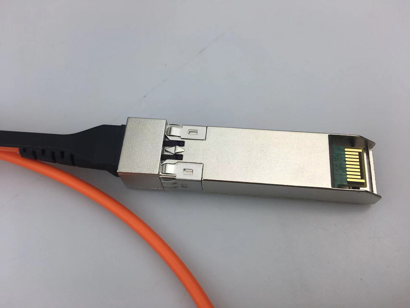
Ø All-metal Housing for Superior EMI Performance
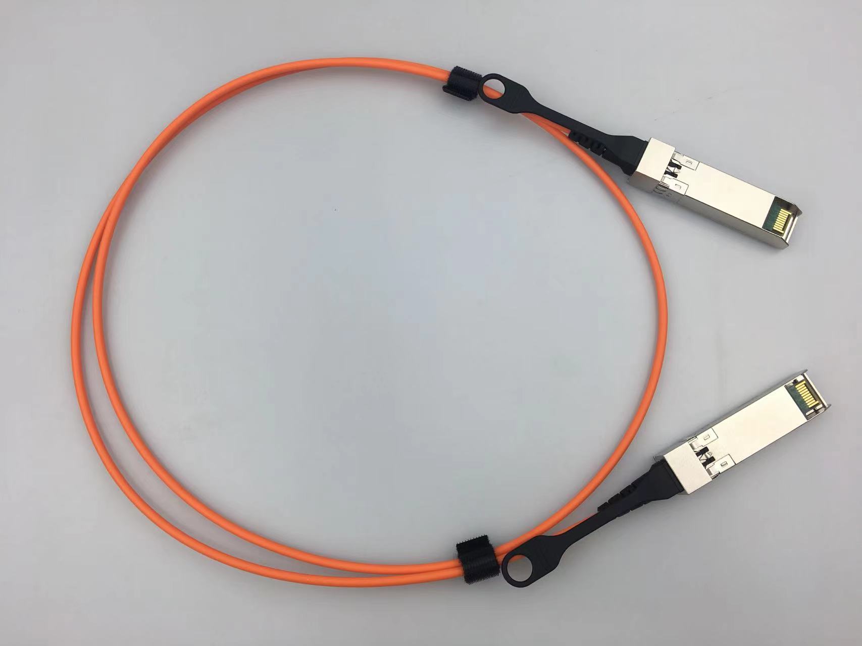
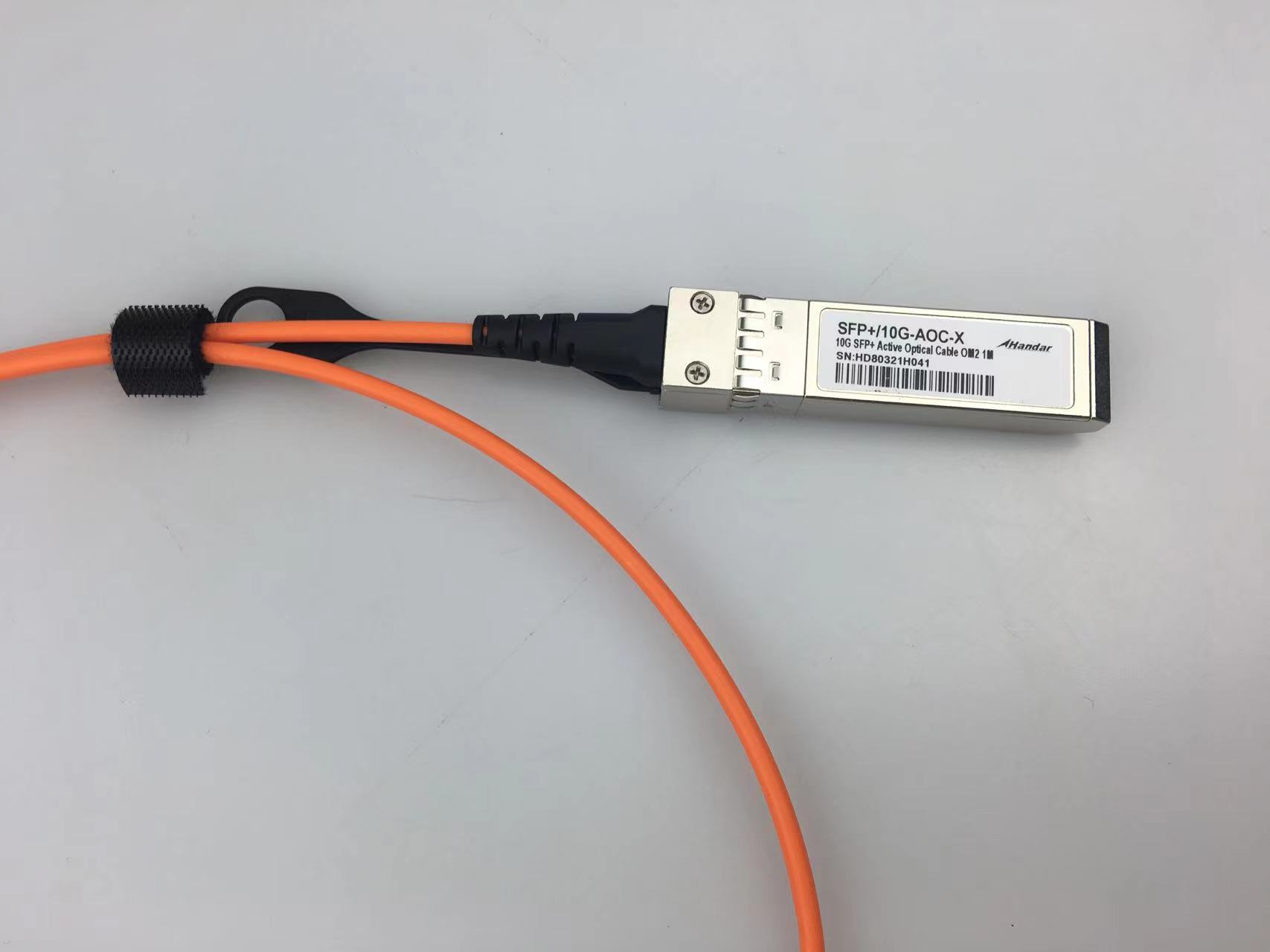
3. Description
Whandar's SFP+ Active Optical Cable (AOC) is a 10Gbps solution to10G Ethernet, and datacenter. The integrated cable transmits 10Gbps data in each direction over MMF with distance up to 100m. The AOC is SFP+ MSA compliance, low power consumption and lightweight.
4. standard
Ø Compliant with SFF-8431 and SFF-8432
Ø Compliant with SFF-8472 Rev 10.2
Ø Compliant with IEEE 802.3ae 10GBASE-LR and 10GBASE-LW
Ø RoHS Compliant
5. Performance Specifications
5.1. Absolute Maximum Ratings
These values represent the damage threshold of the module. Stress in excess of any of the individual Absolute Maximum Ratings can cause immediate catastrophic damage to the module even if all other parameters are within Recommended Operating Conditions.
Table.1 Absolute maximum ratings
Parameter | Symbol | Min | Max | Units |
Storage temperature | Ts | -20 | 85 | ℃ |
Relative Humidity | RH | 5 | 85 | % |
Supply Voltage | Vc | -0.3 | 3.6 | V |
Supply Current | Icc |
| 450 | mA |
5.2. Recommended Operating Conditions
Table.2 Recommended Operating Conditions
Parameter | Symbol | Min | Typical | Max | Unit |
Operating Case Temperature | Standard Tc | 0 | 25 | 70 | °C |
Power Supply Voltage | Vcc | 3.13 | 3.3 | 3.47 | V |
Power Supply Current | Icc |
| 60 | 260 | mA |
Power Dissipation | PD |
| 600 | 800 | mW |
Data Rate | DR |
| 10.3125 |
| Gbps |
Transmission Distance | TD |
|
| 100 | m |
5.3. Transmitter Specification
Table.3 Transmitter Specification (Optical)
Parameter | Symbol | Min. | Typ. | Max. | Unit | Note |
Average Output Power | Po | -5 |
| -1 | dBm |
|
Disable Power | Poff |
|
| -40 | dBm |
|
Extinction Ratio | ER | 3.5 |
|
| dB |
|
Output Centre Wavelength | λc | 840 |
| 860 | nm |
|
Table.4 Transmitter Specification (Electrical)
Parameter | Symbol | Min | Typical | Max | Unit |
Data Input Swing Differential | VIN | 200 |
| 700 | mV |
Input Differential Impedance | ZIN | 90 | 100 | 110 | Ω |
Transmit Disable Input | High | VIH | 2.0 |
| Vcc+0.3 | V |
Low | VIL | 0 |
| 0.8 | V |
5.4. Receiver Specification
Table.5 Receiver Specification (Optical)
Parameter | Symbol | Min | Typical | Max | Unit | note |
Centre Wavelength | λc | 840 | 850 | 860 | nm |
|
Receiver Sensitivity | Sen |
|
| -11 | dBm | 1 |
Receiver Overload | Psat | 0.5 |
|
| dBm | 1 |
LOS De-Assert | LOSD |
|
| -15 | dBm |
|
LOS Assert | LOSA | -30 |
|
| dBm |
|
LOS Hysteresis |
| 0.5 |
| 4 | dB |
|
Receiver Reflectance | Rrx |
|
| -12 | dB |
|
Note :1. Measured at BER 10-12, 10.3Gbps, PRBS2^31-1, NRZ
Table.6 Receiver Specification (Electrical)
Parameter | Symbol | Min | Typical | Max | Unit | note |
Data Output Swing Differential | Vout | 300 |
| 800 | mV |
|
Rx-Los Fault | Vlf | 2.0 |
| VccHOST | V |
|
Rx-Los Normal | Vln | 0 |
| 0+0.8 | V |
|
Output rise and fall time | Tr, Tf | 28 |
|
| ps |
|
5.5. Diagnostics Specification
Table.7Diagnostics Specification
Parameter | Range | Unit | Accuracy | Calibration |
Temperature | 0 to 70 | ℃ | ±3℃ | Internal / External |
Voltage | 3.0 to 3.6 | V | ±3% | Internal / External |
Bias Current | 0 to 100 | mA | ±10% | Internal / External |
TX Power | -5 to-1 | dBm | ±3dB | Internal / External |
RX Power | -30to 0 | dBm | ±3dB | Internal / External |
5.6. Pin Definitions


Table.8Pin Definitions
PIN | Symbol | Description | Remarks |
1 | VEET | Transmitter ground (common with receiver ground) | Circuit ground is isolatedfrom chassis ground |
2 | Tx_Fault | Transmitter Fault. Not supported |
|
3 | Tx_Disable | Transmitter Disable. Laseroutput disable on high or open | Disabled: TDIS>2V or open Enabled: TDIS<0.8V |
4 | SDA | 2-wire Serial Interface Data Line | Should Be pulled up with4.7k – 10kohm on hostboard to a voltage between2V and 3.6V |
5 | SCL | 2-wire Serial Interface Clock Line |
6 | MOD_ABS | Module Absent. Grounded within the module. |
7 | RS0 | No connection required |
|
8 | RX_LOS | Loss of Signal indication. Logic 0 indicates normal operation | LOS is open collector output |
9 | RS1 | No connection required |
|
10 | VEER | Receiver ground (common with transmitter ground) | Circuit ground is isolatedfrom chassis ground |
11 | VEER | Receiver ground (common with transmitter ground) |
12 | RD– | Receiver Inverted DATA out. AC coupled |
|
13 | RD+ | Receiver Non-inverted DATA out. AC coupled |
|
14 | VEER | Receiver ground (common with transmitter ground) | Circuit ground is isolatedfrom chassis ground |
15 | VCCR | Receiver power supply |
|
16 | VCCT | Transmitter power supply |
|
17 | VEET | Transmitter ground (common with receiver ground) | Circuit ground is isolatedfrom chassis ground |
18 | TD+ | Transmitter Non-Inverted DATA in. AC coupled |
|
19 | TD– | Transmitter Inverted DATA in. AC coupled |
|
20 | VEET | Transmitter ground (common with receiver ground) | Circuit ground is isolatedfrom chassis ground |
5.9. Mechanical Dimensions

Diagram of Mechanical Dimensions
6. Application Cautions
6.1. ESD
This transceiver is specified as ESD threshold 1kV for high speed pins and 2kV for all other electrical input pins, tested per MIL-STD-883, Method 3015.4 /JESD22-A114-A (HBM). However, normal ESD precautions are still required during the handling of this module. This transceiver is shipped in ESD protective packaging. It should be removed from the packaging and handled only in an ESD protected environment.
6.2. LASER SAFTY
This is a Class 1 Laser Product according to IEC 60825-1:1993:+A1:1997+A2:2001. This product complies with 21 CFR 1040.10 and 1040.11 except for deviations pursuant to Laser Notice No. 50, dated (July 26, 2001)
7. Order Information
Part No. | Description | Rate | Length | Optical Mode |
HD-SFP+/10G-AOC-1 | 10G SFP+ to 10G SFP+ AOC | 10.3G | 1 meter | OM2 |
HD-SFP+/10G-AOC-2 | 10G SFP+ to 10G SFP+ AOC | 10.3G | 2 meters | OM2 |
HD-SFP+/10G-AOC-3 | 10G SFP+ to 10G SFP+ AOC | 10.3G | 3 meters | OM2 |
HD-SFP+/10G-AOC-5 | 10G SFP+ to 10G SFP+ AOC | 10.3G | 5 meters | OM2 |
HD-SFP+/10G-AOC-7 | 10G SFP+ to 10G SFP+ AOC | 10.3G | 7 meters | OM2 |


 sales@huahanda.com
 0755-86654236