点击查看大图

规格书下载产品详情
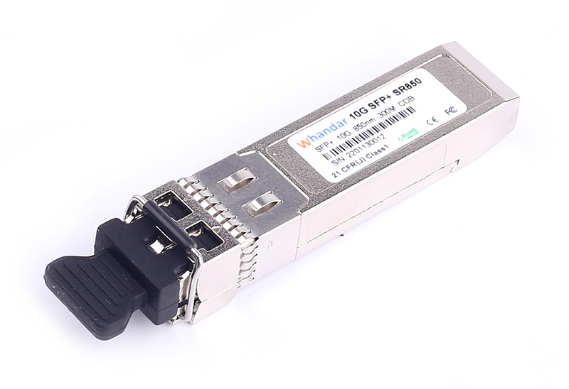
产品介绍
产品特性
1、热插拔SFP封装
2、双纤LC接口
3、在多模光纤中传输距离达到300米
4、内置数字诊断功能
5、符合SFP MSA标准
6、+3.3V单供电电压
7、符合RoHS 6标准
8、工作温度范围:
商业级:0 to +70°C
工业级:-40 to +85°C
9、兼容性强,适用于国内外各品牌交换机
产品应用
1、万兆以太网
2、光纤网络OC-192 同步数字体系STM-64
3、万兆交换机互联
4、万兆路由/服务器光链接
5、其他万兆光传输系统
光学参数
Optical transmitter Characteristics | ||||||
Parameter | Symbol | Min | Typical | Max | Unit | Notes |
Launched Power (avg.) | POUT | -7.3 | -1 | dBm | ||
Optical Power OMA | POMA | -1.5 | dBm | 1 | ||
Operating Wavelength Range | λC | 840 | 850 | 860 | nm | |
Spectral Width (RMS) | ∆λ | 0.45 | nm | |||
Extinction Ratio | ER | 3 | dB | 2 | ||
Transmitter and Dispersion Penalty | TDP | 3.2 | dB | |||
Optical Output Power after TX Disable | PDIS | -30 | dBm | |||
Relative Intensity Noise | RIN | -128 | dB/Hz | |||
Optical Return Loss Tolerance | ORL | 12 | dB | |||
Tx Jitter | Txj | Per IEEE 802.3ae requirements | ||||
Optical Receiver Characteristics | ||||||
Parameter | Symbol | Min | Typical | Max | Unit | Notes |
Wavelength Range | λC | 840 | 850 | 860 | nm | |
Receiver Sensitivity (OMA) | RSENS1 |
-11.1 | dBm | 3 | ||
Stressed Receiver Sensitivity (OMA) | RSENS2 |
-7.5 | dBm | 3 | ||
Optical Power Input Overload | Pin-max | +0.5 | dBm | |||
LOS De-Assert | LOSD | -13 | dBm | 3 | ||
LOS Assert | LOSA | -30 | dBm | 3 | ||
LOS Hysteresis | 0.5 | dB | 4 | |||
Receiver Reflectance | Rr | -12 | dB | |||
Notes:
1.Per Tradeoff Table 52.8, IEEE 802.3ae 2005
2.For the measurements, the device was driven with 231-1 PRBS pattern.
3.Measured with a PRBS 231-1 test pattern, @10.3125Gbps,, BER<10-12
4.The LOS Hysteresis minimizes ‘chatter’ on the output line. In principle, Hysteresis alone does not guarantee chatter-free operation.
引脚定义
The SFP+ modules are hot-pluggable. Hot pluggable refers to plugging in or unplugging a module while the host board is powered. The SFP+ host connector is a 0.8 mm pitch 20 position right angle improved connector specified by SFF-8431, or stacked connector with equivalent electrical performance. SFP+ module contacts mates with the host in the order of ground, power, followed by signal as illustrated by Figure 1 and the contact sequence order listed in Table 1.

Figure 1 SFP+ Pad Assignment Top View
Pin No | Symbol | Name/Description | Power Seq. | Note |
1 | VeeT | Transmitter Ground | 1st | 1 |
2 | TX_Fault | Transmitter Fault | 3rd | 2 |
3 | TX_Disable | Transmitter Disable | 3rd | 3 |
4 | SDA | 2-Wire Serial Interface Data Line | 3rd | 4 |
5 | SCL | 2-Wire Serial Interface Data Line | 3rd | 4 |
6 | Mod_ABS | Module Absent, Connect to VeeT or VeeR in Module | 3rd | 5 |
7 | RS0 | No connection required | 3rd | 6 |
8 | RX_LOS | Receiver Loss of Signal indication | 3rd | 7 |
9 | RS1 | No connection required | 3rd | 8 |
10 | VeeR | Receiver Ground | 1st | 1 |
11 | VeeR | Receiver Ground | 1st | 1 |
12 | RD- | Receiver Inverted DATA out. AC Coupled. CML-O | 3rd | 9 |
13 | RD+ | Receiver Non-inverted DATA out. AC Coupled. CML-O | 3rd | 9 |
14 | VeeR | Receiver Ground | 1st | 1 |
15 | VccR | Receiver Power Supply | 2nd | 10 |
16 | VccT | Transmitter Power Supply | 2nd | 10 |
17 | VeeT | Transmitter Ground |
<10G-LR-万兆单模光模块 10G-ZR-80KM-万兆光模块> 返回
菜单产品中心Product center |


 0755-86654236