Product Description
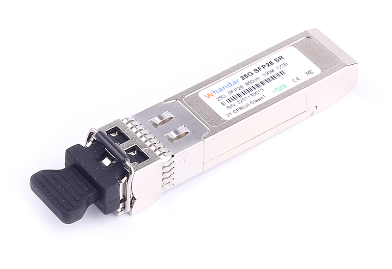
◆ Hot-pluggable SFP28 form factor
◆ Supports 25.78125Gb/s bit rate
◆ Maximum link length of 70m on OM3 MMF and 100m on OM4 MMF
◆ 850nm VCSEL laser and PIN photo detector
◆ Internal CDR on both Transmitter and Receiver channel
◆ Operating environment temperature range: 0 ~ +70℃
◆ Single 3.3V power supply
◆ Low power dissipation: <1.0W
Features
◆ Duplex LC connector Support up to 28Gb/s bit rates
◆ Hot-pluggable SFP footprint
◆ Built-in digital diagnostic functions
◆ Internal CDR on both Transmitter and Receiver channel
◆ Transmission distance up to 100m on OM4 MMF
◆ Single power supply 3.3V
◆ RoHS6 compliant
◆ Operating temperature range Commercial :0℃ to 70℃ Industrial :-40℃ to 85℃
◆ Power consumption <1.0W
Applications
◆ Data Center
◆ 25GBASE-SR Ethernet
◆ 32G Fiber Channel Applications
◆ Servers, Switches, Storage and Host Card Adapters
Optical transmitter Characteristics |
Parameter | Symbol | Min | Typical | Max | Unit | Notes |
Launched Power (avg.) | POUT | -8.4 |
| 2.4 | dBm |
|
Optical Power OMA | POMA | -6.4 |
| 3 | dBm |
|
Operating Wavelength Range | λC | 840 | 850 | 860 | nm |
|
Spectral Width (RMS) | ∆λ |
|
| 0.6 | nm |
|
Extinction Ratio | ER | 2 |
|
| dB |
|
Transmitter and Dispersion Penalty | TDP |
|
| 4.3 | dB |
|
Optical Output Power after TX Disable | PDIS |
|
| -30 | dBm |
|
Relative Intensity Noise | RIN |
|
| -128 | dB/Hz |
|
Optical Return Loss Tolerance | ORL |
|
| 12 | dB |
|
Optical Receiver Characteristics |
Parameter | Symbol | Min | Typical | Max | Unit | Notes |
Wavelength Range | λC | 840 | 850 | 860 | nm |
|
Average Receiver Power | Pmax | -10.3 |
| 2.4 | dBm |
|
Receiver Sensitivity (Average power) | Psen |
|
| -10.3 | dBm | 1,2 |
LOS De-Assert | LOSD |
|
| -13 | dBm |
|
LOS Assert | LOSA | -30 |
|
| dBm |
|
LOS Hysteresis |
| 0.5 |
|
| dB |
|
Receiver Reflectance | Rr |
|
| -12 | dB |
|
Notes:
1. Measured with a PRBS 231-1 test pattern, @25.78125Gb/s, BER<5E-5.
2. Minimum value is informative, equals min Tx OMA with infinite ER and max channel insertion loss.
Pin definition
The SFP28 modules are hot-pluggable. Hot pluggable refers to plugging in or unplugging a module while the host board is powered. The SFP28 host connector is a 0.8 mm pitch 20 position right angle improved connector specified by SFF-8431, or stacked connector with equivalent electrical performance. SFP28 module contacts mates with the host in the order of ground, power, followed by signal as illustrated by Figure 1 and the contact sequence order listed in Table 1.

Figure 1 SFP28 Pad Assignment Top View
Pin No | Symbol | Name/Description | Power Seq. | Note |
1 | VeeT | Transmitter Ground | 1st | 1 |
2 | TX_Fault | Transmitter Fault | 3rd | 2 |
3 | TX_Disable | Transmitter Disable | 3rd | 3 |
4 | SDA | 2-Wire Serial Interface Data Line | 3rd | 4 |
5 | SCL | 2-Wire Serial Interface Data Line | 3rd | 4 |
6 | Mod_ABS | Module Absent, Connect to VeeT or VeeR in Module | 3rd | 5 |
7 | RS0 | No connection required | 3rd | 6 |
8 | RX_LOS | Receiver Loss of Signal indication | 3rd | 7 |
9 | RS1 | No connection required | 3rd | 8 |
10 | VeeR | Receiver Ground | 1st | 1 |
11 | VeeR | Receiver Ground | 1st | 1 |
12 | RD- | Receiver Inverted DATA out. AC Coupled. CML-O | 3rd | 9 |
13 | RD+ | Receiver Non-inverted DATA out. AC Coupled. CML-O | 3rd | 9 |
14 | VeeR | Receiver Ground | 1st | 1 |
15 | VccR | Receiver Power Supply | 2nd | 10 |
16 | VccT | Transmitter Power Supply | 2nd | 10 |
17 | VeeT | Transmitter Ground | 1st | 1 |
18 | TD+ | Transmitter Non-Inverted DATA in. AC Coupled. CML-I | 3rd | 11 |
19 | TD- | Transmitter Inverted DATA in. AC Coupled. CML-I | 3rd | 11 |
20 | VeeT | Transmitter Ground | 1st | 1 |
Power Seq.: Pin engagement sequence during hot plugging.
Notes:
1. The module signal ground contacts.
2. This pin is an open drain/collector and should be pulled up to Vcc-host in the host with a 4.7k~10k Ohm resistor.
3. This pin should be pulled up to VccT with a 4.7k~10k Ohm resistor in modules.
4. SDA&SCL (IIC) are needed pull up 4.7k~10k Ohm resistors on host board.
5. Mod_ABS is connected to VeeT or VeeR in the SFP28 module.
6. Rate Select 0, no connection required.
7. Module RX_Los of signal indication need pull up 4.7k~10k Ohm resistor on host board.
8. Rate Select 1, no connection required.
9. RD -/+: These are the differential receiver outputs. They are CML AC-coupled with 100 Ohm terminal resistor matching internal.
10. VccR and VccT are the receiver and transmitter power supplies.
11. TD-/+: These are the differential transmitter inputs. They are CML AC-coupled with 100 Ohm terminal resistor matching internal
Ordering information
PART NO. | Specifications |
Pack | Rate | Tx | Po | Sen | Temp | Reach | DDM |
(Gbps) | (nm) | (dBm) | (dBm) | (℃) | (m) |
HD-SFP28/25G-SR | SFP28 | 25.78125 | 850 | -8.4~2.4 | <-10.3 | 0~70 | 100 | Y |
*Note:
1. Measured with a PRBS 231-1 test pattern, @25.78125Gb/s, BER<5E-5.
2. OM3 Cable length =<70m or OM4 Cable length =<100m.
3. More detail product selection and cable lengths, please contact Handar.


 sales@huahanda.com
 0755-86654236